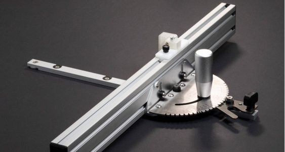
My Metabo table saw has a decent miter gauge, but the fence on it is a bit flimsy, and it lacked a flip stop. So I came up with this simple project to add a solid aluminium extrusion and a 3d-printed flip stop to it. I’ve also recently purchased a better miter gauge for my router table, so I wanted it to be able to fit that one as well.
All parts together, it only cost me about €15. That’s hard to beat, even for AliExpress!
Below you’ll find a step-by-step guide on how to make one of these flip stop fences yourself. You can download the 3D print files by clicking the download button at the top of the page.
The design is really simple. The only ‘special’ thing about it is the two teeth on the flip stop. These fall perfectly into the slots on the 3060 extrusion, which eliminates any play. Usually flip stops of this design have some lateral play, which makes them inaccurate for repeated cuts. By adding these two teeth, it stays in place even if you push hard against them with your workpiece.
Parts required:
Tools required:
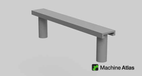
Making the fence really consists of only one step… going online and ordering an aluminium extrusion. The one I use is a standard 3060 profile, 600 mm long, but you can use any length that you find practical for your setup.
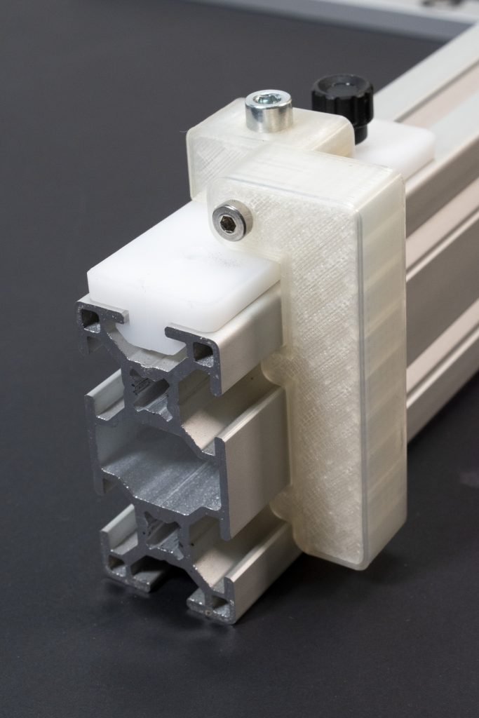
I’ve ordered mine from Aluxprofiel.nl, here in the Netherlands. I think it’s an industry standard profile (see image below), so you can purchase it somewhere else too. Do double check that the profile is the same though, as the 3D printed part has been designed to fit exactly this specific profile.
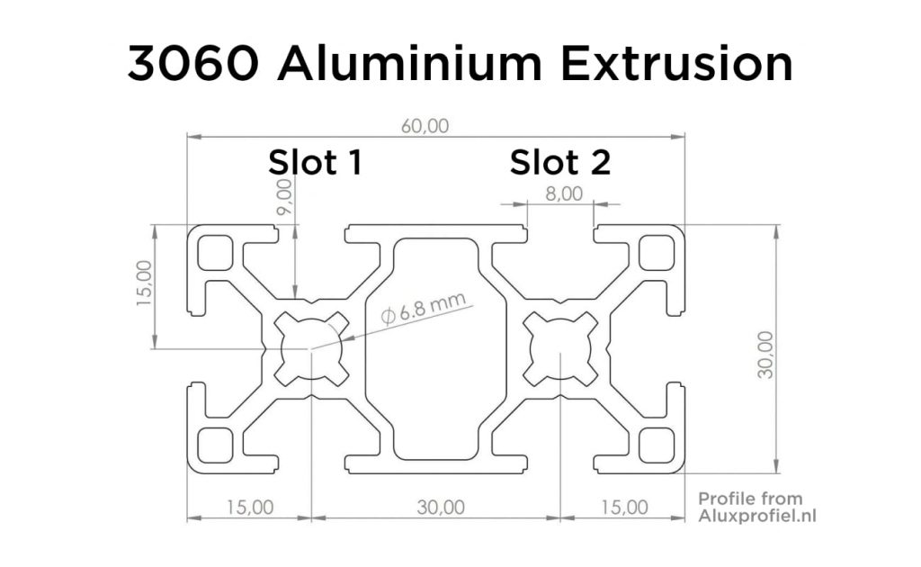
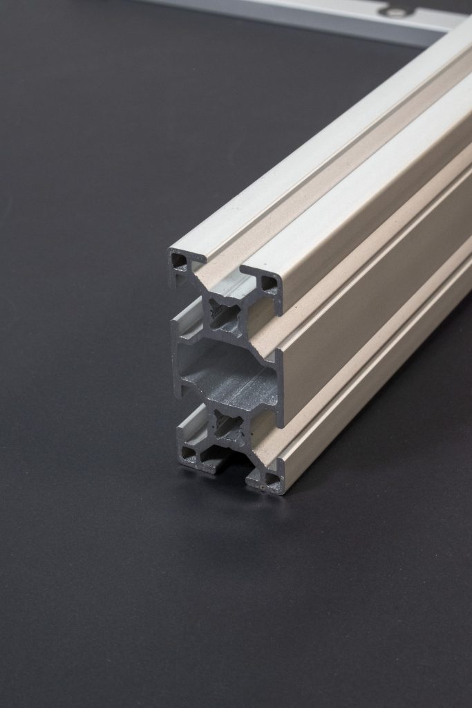
What’s great about this 3060 extrusion is that it has two slots vertically, so that way you can attach it to miter gauges that have the connecting bolts positioned high (like on my table saw), or if they’re positioned low (like on my new miter gauge).
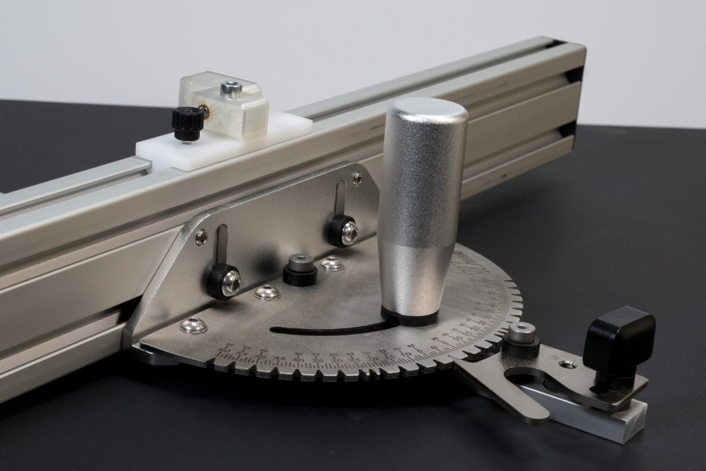
Attaching the extrusion to the miter gauge is simple in most cases. Just slide the connecting bolts into the extrusion’s slots and tighten them.
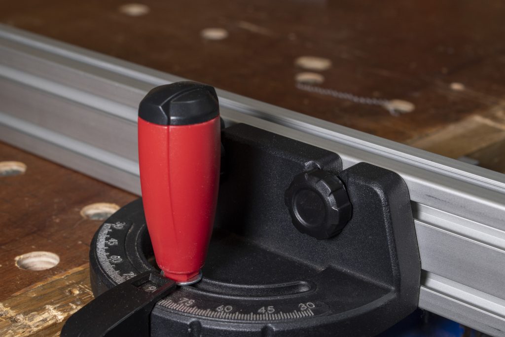
One advantage of my new miter gauge is that it has two set screws for adjusting the angle of the fence. This way you can set it to perfectly 90 degrees to the table. On my Metabo miter gauge this isn’t possible, but it was square anyway. Alternatively you could shim it, which should work just as well (although more fiddly).
Parts required:
Tools required:
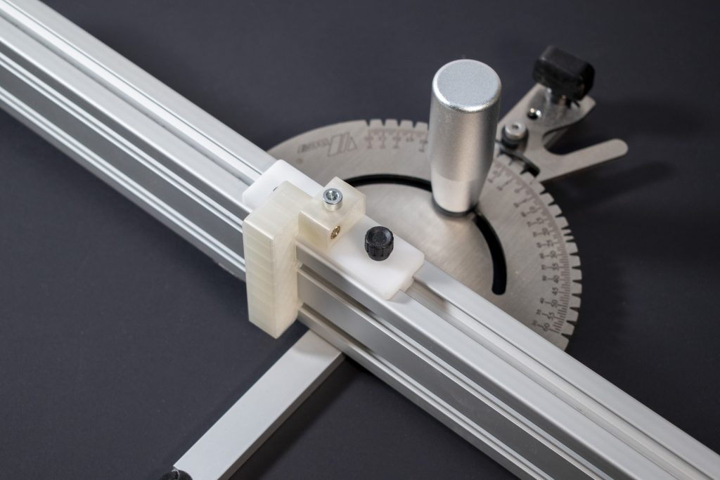
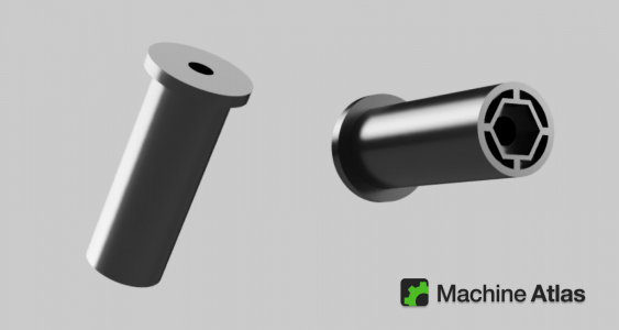
To make the flip stop element, you’ll need all the parts listed above. The bolts and knob are all generic parts. I’ve linked to where I’ve purchased them, but any equivalent versions will do the job. The only special part required is the glide block.
I’ve purchased this at the same place where I got my extrusion (aluxprofiel.nl), and it’s made specifically for this extrusion profile. You could also choose to 3D print this part, but the advantage of this block is that it’s made of a special type of plastic, called POM. This plastic is very durable, slides smoothly, and can be tapped without risk of breakout.
If you can’t find this part anywhere, you can 3D print it yourself using the STEP file I’ve added the download folder (or download it directly here). In that case you will need to adjust the holes, and add two threaded inserts yourself. Adding the thread in the model, or tapping PLA or ABS yourself aren’t strong enough in the long term in my opinion, especially with smaller threads like M4 or M5.
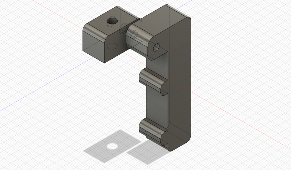
The flip stop consists of two 3D printed parts: the base, which attaches to the glide block, and the flip stop arm itself. Download the files here.
I’ve printed these parts on my Prusa Mini with a 0.6 mm nozzle, so the tolerances are tuned for that setup. If you use a different printer, or a different nozzle size, you may have to tweak your print settings slightly to get the perfect fit.
Personally I’ve printed it with PLA, but if are able to use a stronger material like ABS, that would be even better, as it’s more durable in the long term.
To attach both the knob and the flip stop to the glide block, it will need to have two threaded holes. One M5 hole for the flip stop, and one M4/M5/M6 hole for the knob or lever, depending on the specific size you picked. I had an M4 knob lying around, but an M5 one would probably be slightly sturdier. M6 would also work.
The pre-drilled holes in the glide block are small (2-3 mm), so you’ll need to drill them out more before tapping. In the case of M4, about 3 to 3.5 mm works well, and for M5, 4 to 4.5 mm bits will do the job. It’s not essential to get this perfect, as the plastic is much softer than metal and will tap easily even if the hole is a bit too small. Don’t oversize it though.
After drilling the holes, add threads to them with a hand tap.
The flip stop arm is attached to the base with a 30 mm M4 bolt. But the 3D printed part has no thread yet, so we’ll need to add that, using a threaded insert. These are extremely solid and a great way to add threaded holes to 3D prints. CNC Kitchen has a great video on them if you’re interested.
The hole in the base has two open sides, one being larger. The insert should go into the larger hole.
Heat up your soldering iron, push the threaded insert into the hole as far as you can by hand, and then push it in using the soldering iron. The heat of the iron will melt the plastic around it, allowing the insert to sink in. Once it’s fully in, remove the iron. The plastic will immediately solidify, and the insert is locked tight.
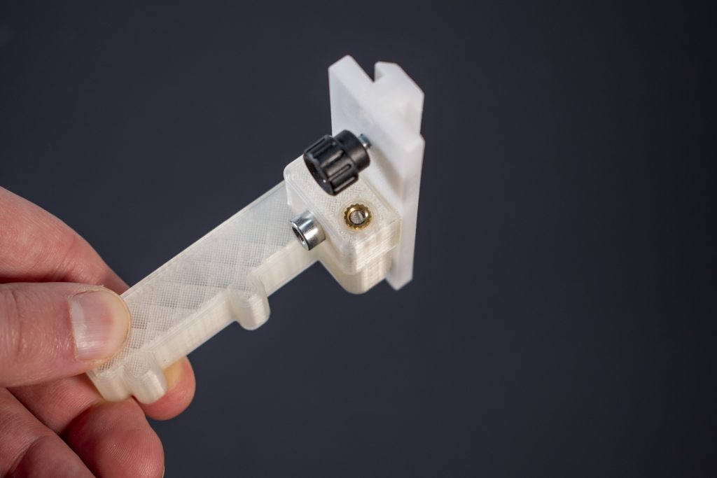
Now it’s just a question of assembling all parts. The M5 bolt goes through the base, into the glide block. The 30 mm M4 bolt goes through the flip stop arm and into the base, screwing into the threaded insert.
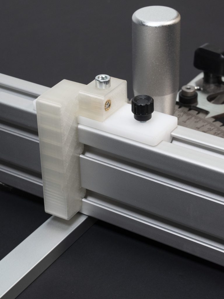
The knob or lever goes into the glide block. With all these parts put together, you can slide the glide block into top slot of the aluminium extrusion. You can lock it in place by tightening the knob.
One additional option is to add a little bit of felt or some other soft material to the bottom of the knob or lever. This prevents damaging the aluminium every time you lock the flip stop.
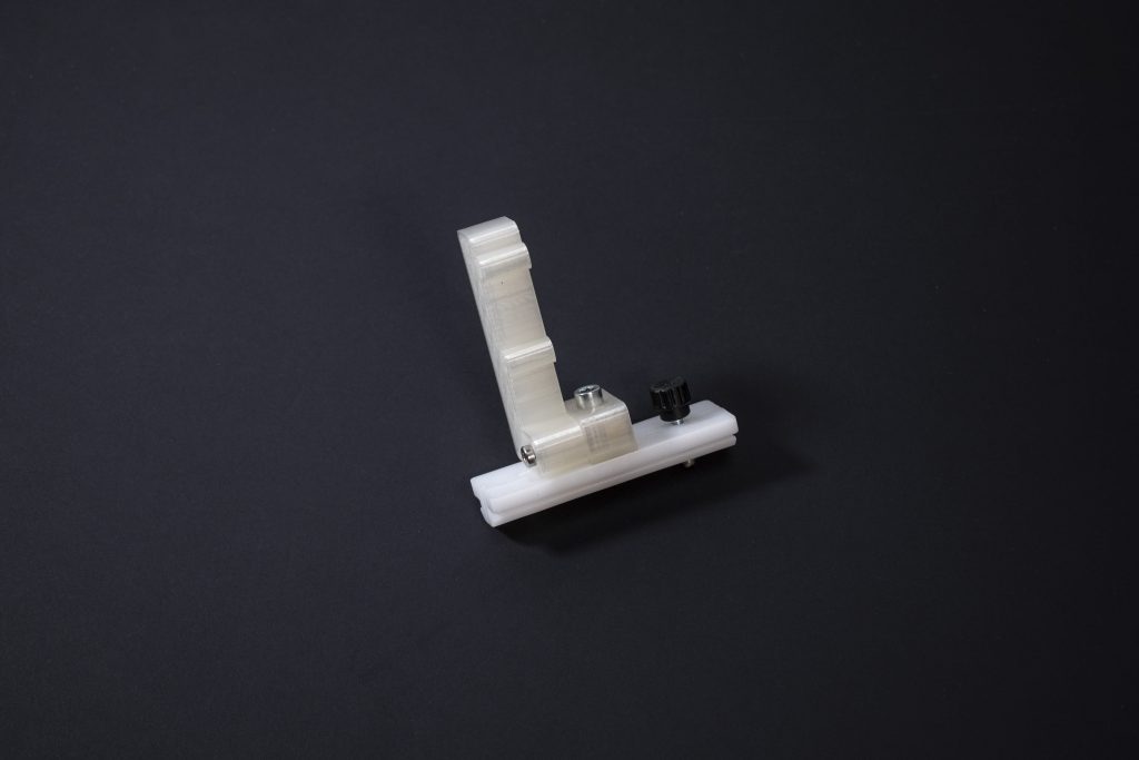
I think the design works quite well in practice. The 3060 extrusion is solid, the glide block moves smoothly, locks solidly, and the flip stop has no movement laterally. However, I can still see a few possible improvements.
One minor downside is currently that the base block is only held by a single bolt. This allows it to rotate freely, unless it is secured extremely tightly. With two bolts, it would prevent any movement at all. Alternatively, if the whole thing was designed as one 3D printed part (so the base and the glide block being one piece), it would be more solid too.
Another small issue is that when you secure the knob, the glide block becomes slightly angled. This also makes the flip stop arm slightly angled. You can test this by holding a square next to it, and you’ll see it’s kind of at an angle.
A potential solution for this is to design the glide block and arm as one piece, and then having the locking knob exactly in the middle. I might design this improved version some time, and if I do I’ll update it here.
If you have any other suggestions for improvements, let me know, I’d be happy to implement them!
Trying to make a perfectly round mast? With this spar gauge you can turn any square stock into an 8-sided beam. […]
Trying to make a perfectly round mast? With this spar gauge you can turn any square stock into an 8-sided beam. […]
3D Printed Planing Stop This is a simple planing stop that works with two bench dogs from the ‘Atlas System’ […]
3D Printed Bench Dogs These are the basic bench dogs I have designed for what I call the ‘Atlas System’ […]
© Machine Atlas 2026
There are no comments yet, be the first to leave one!
Every comment on MachineAtlas is read and answered. And if you know some useful info or tips, please share them. You could really help out some fellow woodworkers!